


论文题目:Routing performance analysis 论文语言:英语论文 English 代写价格:0 论文专业:IT 字数:3 pages 学校国家:澳大利亚 是否有数据处理要求:否 您的学校: 论文用于:BA assignment 本科课程作业 Page 1 of 8 COMP 3331/9331: Computer Networks & Applications Programming Assignment: Routing Performance Analysis Due Date: Friday 25 Oct 2013, 11:59 pm (Week 12) Change Log a. Version 1.0 released on September 17th, 2013 b. Version 1.1 released on September 19th, 2013 A missing link in Figure 1 was added. Additional notes changed: Assignment can be done in a group of two. Assessment: 60 marks (towards the Practical component) Goal: The purpose of this assignment is to gain insights into the performance of different network-layer routing algorithms. Your task is to develop a program that will evaluate the performance of 3 different routing protocols over a virtual circuit network (i.e. a network with a connection-based network layer, unlike the Internet) Learning Objectives: On completing this assignment you will gain sufficient expertise in the following skills: • Understanding and developing routing protocols • Performance analysis Specification: You will implement the following program: Routing_Performance • The routing_performance program will accept the following command line arguments: o ROUTING_SCHEME: this specifies the routing scheme that will be evaluated. Your program should implement 3 routing protocols, which are essentially variants of Dijkstra’s algorithm, as explained later in the specification. This argument will take on one of the following values: SHP, SDP and LLP corresponding to the 3 routing protocols: Shortest Hop Path (SHP), Shortest Delay Path (SDP) and Least Loaded Path (LLP), respectively. o TOPOLOGY_FILE: this file contains the network topology specification. o WORKLOAD_FILE: this file contains the virtual circuit requests in the network. • The network topology that will be used for the evaluation will be specified in the TOPOLOGY_FILE (the second argument). We will be using a virtual circuit network (unlike the connection-less network layer of the Internet) to evaluate the performance of the routing protocols. Recall that a routing protocol is still required in a virtual-circuit network to determine the path between the source and destination of the circuit during Page 2 of 8the circuit establishment phase. A simple example of a network topology specification for a network with 4 routers (routers will be referred to as nodes in the rest of the specification), labelled A, B, C and D is as follows: A B 10 19 A C 15 20 B C 20 20 B D 30 70 C D 8 20 This example network topology has 5 links connection the 4 nodes as shown in the figure below (Figure 1 on the next page). Each line in this file defines a point-to-point link. For example, the first line specifies a link from node A to node B, with a one-way propagation delay of 10 这个例子的网络拓扑结构有5个环节,连接4个节点,在下面的图(下页图1)所示。在这个文件中的每一行定义一个点至点链接。例如,第一行指定一个链接从节点A到节点B,用一个单向传播延迟为10milliseconds and a capacity that can accommodate up to 19 simultaneous virtual circuits at any given time. All links are assumed to be bi-directional, with identical propagation delay in both directions (hence, the ordering of the names of the two endpoints of the point-to-point link does not matter, i.e. the first line in the example above could have been replaced with “B A 10 19”). Further, each virtual circuit is also assumed to be bi-directional and consumes unit resource (i.e. a resource of 1). 所有链路被认为是双向的,在两个方向上具有相同的传播延迟(因此,在点对点链路的两个端点的名称的顺序并不重要,即在上面的例子中可以在第一行已取代与“ BA 10月19日” ) 。另外,每个虚拟电路也假定为双向的,消耗单元资源(即资源的1 ) 。 将有至多有一个图中的任意两个节点之间的直接联系。你可以假设,即将不会有孤立节点的拓扑结构将形成一个连通图。 你的程序的第一个任务是读取拓扑文件和使用合适的数据结构,构造一个合适的网络拓扑结构,内部表示。你可能想咨询的标准数据结构无向图,这将是一个合适的方法来模拟网络标准声明教科书。你可以假设所有的节点名称是大写字母(即从A到Z ,最多26个节点) ,所有的传播延迟d是正整数( 0 <D < 200 ) ,并表示以毫秒为单位,所有链接容量C为正整数( 0 <C < 100 ) ,表示虚拟电路可以得到的链接数量。一个更复杂的网络拓扑结构,用于测试你的代码,你可以使用分配的网页( topology.txt )上。 There will be at most one direct link between any two nodes in the graph. You may assume that the topology will form a connected graph i.e. there will be no isolated nodes. The first task for your program is to read in the topology file and construct a suitable internal representation of the network topology, using an appropriate data structure. You may want to consult standard data structures textbooks for standard representations of undirected graphs, which would be an appropriate way to model the network. You may assume that all node names are single upper-case alphabetic characters (i.e., a maximum of 26 nodes from A to Z), all propagation delays d are positive integers (0 < d < 200) and expressed in milliseconds, and all link capacities C are positive integers (0 < C < 100) and indicate the number of virtual circuits that can be supported by a link. A more complex network topology, which you may use for testing your code is available on the assignment webpage (topology.txt).
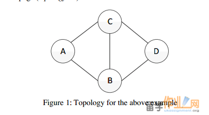 Figure 1: Topology for the above example
• The network is initially empty, i.e., there are no virtual circuits established. The virtual circuit requests that arrive in the network will be specified in the WORKLOAD_FILE (third argument), which is ordered by time. The next step for your program is to read in the arriving virtual circuit request workload (from the file), one request at a time, in timestamp order, and attempt to establish the circuit in the network according to the routing algorithm in use (routing algorithms are explained later). The virtual circuit workload for the network is specified in a simple four-column format as follows:Page 3 of 8
0.123456 A D 12.527453
7.249811 B C 48.129653
8.975344 B D 6.124743
10.915432 A C 106.724339
15.817634 B C 37.634569
Each line of this file describes one virtual circuit request. The first column specifies the time (in seconds) at which the request arrives to the network. You may assume that time starts at 0 seconds and that time values will be represented up to 6 decimal digits (i.e. microseconds). The second column specifies the originator (source node) for the request, and the third column specifies the recipient (destination node) for the request. The final
column specifies the time duration for which this virtual circuit remains active if the circuit is successfully established. As an example, the first line in the above file contains a request that originated at time 0.123456 seconds for a virtual circuit to be established from node A to node D. This circuit if established will be active for a duration of 12.527453 seconds. A more comprehensive virtual circuit workload, which you may use for testing your program, is available on the assignment webpage in the workload.txt file. (Note that, this workload is consistent with the topology specified in topology.txt)
• For each virtual circuit request in the above workload, your program must use the specified routing algorithm to determine if the circuit can be established. To be more specific, your program must select the “best” route depending on the routing protocol in use (routing protocols are explained in the next bullet point) from the source to the destination of the circuit and then determine if there is sufficient capacity along each link of this end-to-end path to accommodate the circuit. Recall that each virtual circuit uses unit capacity on each link. You may assume that the routing decision for each request can be made in zero processing time. A virtual circuit that is successfully established must be counted as such, and the network resources associated with that circuit marked as "busy" for the duration of the circuit. For this purpose, assume that each circuit consumes exactly one unit (i.e., one "circuit") of link capacity on each link. Of course, recall that virtual circuits are bidirectional. When a circuit terminates, the resources (i.e.
unit capacity) along the individual links of the end-to-end path are released, and become available for subsequent circuits that are established in the network. A circuit request that is not routed successfully is said to be "blocked". A blocked request means that there is no physical path currently available from the specified source to the specified destination
Figure 1: Topology for the above example
• The network is initially empty, i.e., there are no virtual circuits established. The virtual circuit requests that arrive in the network will be specified in the WORKLOAD_FILE (third argument), which is ordered by time. The next step for your program is to read in the arriving virtual circuit request workload (from the file), one request at a time, in timestamp order, and attempt to establish the circuit in the network according to the routing algorithm in use (routing algorithms are explained later). The virtual circuit workload for the network is specified in a simple four-column format as follows:Page 3 of 8
0.123456 A D 12.527453
7.249811 B C 48.129653
8.975344 B D 6.124743
10.915432 A C 106.724339
15.817634 B C 37.634569
Each line of this file describes one virtual circuit request. The first column specifies the time (in seconds) at which the request arrives to the network. You may assume that time starts at 0 seconds and that time values will be represented up to 6 decimal digits (i.e. microseconds). The second column specifies the originator (source node) for the request, and the third column specifies the recipient (destination node) for the request. The final
column specifies the time duration for which this virtual circuit remains active if the circuit is successfully established. As an example, the first line in the above file contains a request that originated at time 0.123456 seconds for a virtual circuit to be established from node A to node D. This circuit if established will be active for a duration of 12.527453 seconds. A more comprehensive virtual circuit workload, which you may use for testing your program, is available on the assignment webpage in the workload.txt file. (Note that, this workload is consistent with the topology specified in topology.txt)
• For each virtual circuit request in the above workload, your program must use the specified routing algorithm to determine if the circuit can be established. To be more specific, your program must select the “best” route depending on the routing protocol in use (routing protocols are explained in the next bullet point) from the source to the destination of the circuit and then determine if there is sufficient capacity along each link of this end-to-end path to accommodate the circuit. Recall that each virtual circuit uses unit capacity on each link. You may assume that the routing decision for each request can be made in zero processing time. A virtual circuit that is successfully established must be counted as such, and the network resources associated with that circuit marked as "busy" for the duration of the circuit. For this purpose, assume that each circuit consumes exactly one unit (i.e., one "circuit") of link capacity on each link. Of course, recall that virtual circuits are bidirectional. When a circuit terminates, the resources (i.e.
unit capacity) along the individual links of the end-to-end path are released, and become available for subsequent circuits that are established in the network. A circuit request that is not routed successfully is said to be "blocked". A blocked request means that there is no physical path currently available from the specified source to the specified destination  15012858052
 153688106
